2001 Toyota Prius NHW11 battery swap
 |
DANGER: If you make a mistake while working on this battery,
you will die.
DANGER: Hazardous voltage. Contact will cause electric shock,
burn, or death.This traction battery pack can deliver over
100 amperes at over 270 volts DC.
DISCLAIMER
- These photos and descriptions are provided for information
only. Do not attempt.
- This Web page is NOT created by, sponsored by, endorsed by,
affiliated with, or otherwise connected to Toyota Motor
Corporation, Toyota Motor Sales USA Inc, any other Toyota
subsidiary, any Toyota dealership, Panasonic EV Energy Co. Ltd, or
Primearth EV Energy Co. Ltd.
- The creator of this Web page, other than owning a 2001 Toyota
Prius, has NO CONNECTION with Toyota Motor Corporation, Toyota
Motor Sales USA Inc, any other Toyota subsidiary, any Toyota
dealership, Panasonic EV Energy Co. Ltd, or Primearth EV Energy Co.
Ltd.
- The Prius shown here, and its original battery, were produced
in June 2000 for the United States market. The parts in cars
produced at other times or for other markets will vary.
|
|
These photos were taken by me with a Nikon Coolpix L20 digital camera.
They have been reduced from the original dimensions. The thumbnails are 15 kB
to 50 kB and the large photos are 250 kB to 850 kB.
All thumbnails on this page link to larger versions. Use the "back" button
in your browser to return to this page.
Introduction
In early July, 2010, the original battery in my 2001 Toyota Prius
failed, with about 122,000 miles (196,000 km) on it. I determined that it had
a shorted cell in one of the battery modules. After evaluating the options, I
decided to order a replacement battery from Toyota and swap it myself. The
photos on this page document some aspects of this swap.
There are a few Web sites that offer Toyota parts at a discount from list
price. I found out that one of them was actually operated by a local Toyota
dealer, so I ordered through that site. The Toyota part number is
G9510-47020, and I paid US$1,839.20 for it. Sales tax was about 8.65% or
$159.10, for a total of $1,998.30. I was charged US$69 shipping, but that was
probably because I was close enough to the dealer that they had the battery
delivered to the dealership along with their other orders. They were going to
deliver it to me on their own truck, but I picked it up at their parts
department. If it had been shipped directly to me via UPS ground or FedEx
ground, the shipping charge would probably have been much higher.
References used include:
Toyota manuals:
2001 Prius Repair Manual, Volume 1, RM778U1
2001 Prius Repair Manual, Volume 2, RM778U2
2001 Prius Electrical Wiring Diagram, EWD414U
Prius New Car Features, May, 2000, NCF182U
Technical Instructions for Special Service Campaign 40G
Other manuals:
How to Keep Your Volkswagen Alive: A Manual of Step-by-Step Procedures for
the Compleat Idiot by John Muir
"Don't be fearful, be careful." "FRONT means the front of the car."
Discussion groups:
Prius
Technical Stuff Yahoo! group
"Front" means the front of the car, when the battery is installed in the
car normally. "Driver's side" means the left side of the car.
Tools used
NOTE: This list is incomplete.
- 12 mm and 10 mm sockets
- Ratchet and extensions to suit above sockets
- 8 mm and 10 mm nutdrivers
- Phillips screwdriver
- T30 Torx screwdriver or bit
- Torque wrench capable of 48 INCH-POUNDS, NOT
foot-pounds! (or 5.5 Newton-meters)
- 8 mm socket to suit above torque wrench
- Magnet-on-a-stick (for retrieving ferrous parts)
- Pliers
- Digital voltmeter
- Felt-tip permanent marker
- Kitchen sponge (soft yellow foam with attached green scrubbing
pad)
- Plastic cup (SST QT-32OZ)
- Plastic scraper (plastic knife)
- Hand truck (dolly, two-wheeler)
Supplies used
NOTE: This list is incomplete.
- Plastic sandwich bags
- Distilled white vinegar
- Tap water
- Electrical tape
New battery from Toyota
 |
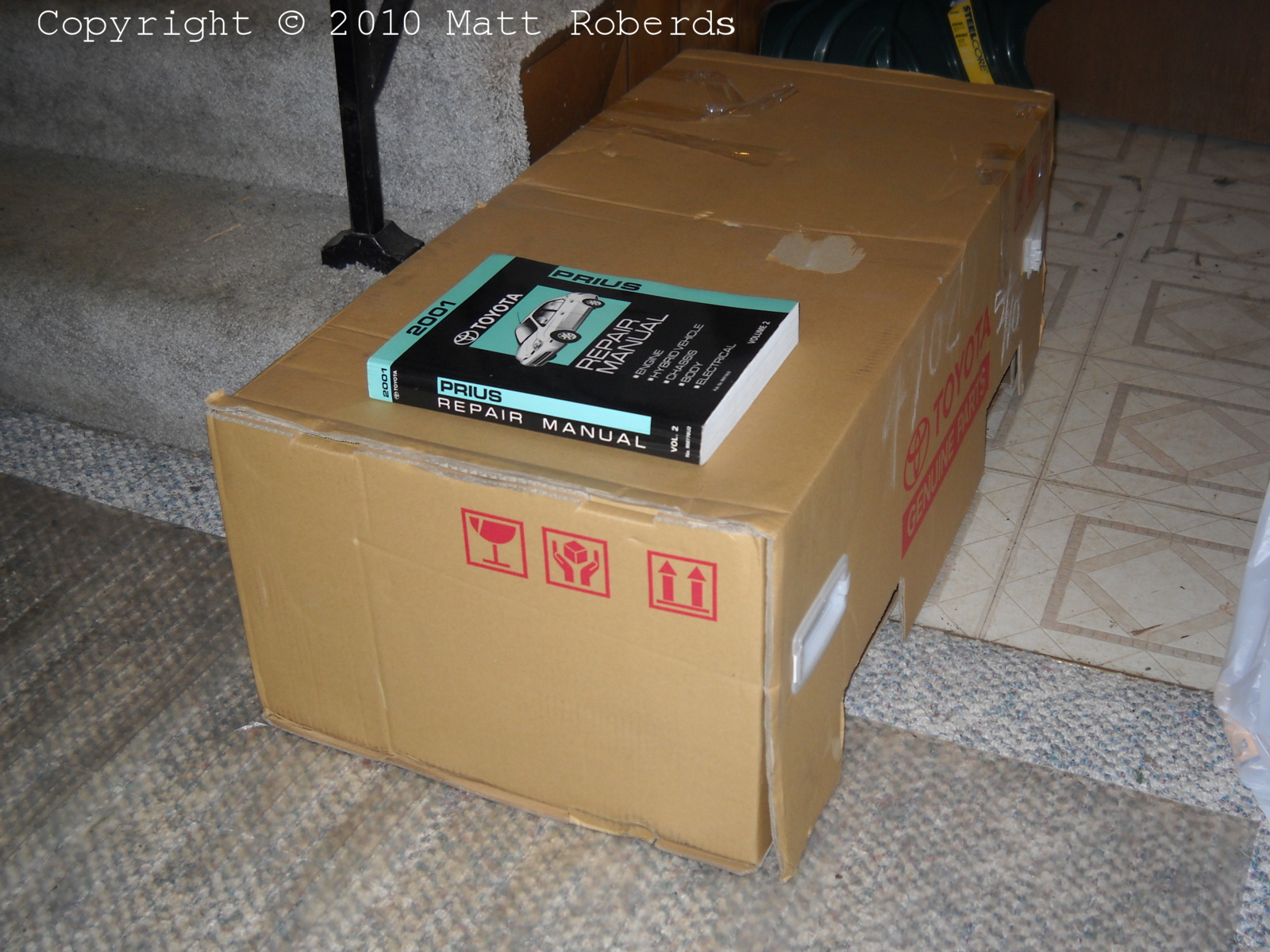
This is the box the new battery comes in, with volume
2 of the repair manual for scale. The box measures about 12.5" H x 39" W
x 18.5" D, or about 32 cm H x 100 cm W x 47 cm D. There are holes in the
sides for a fork truck or pallet jack; the holes are about 2.5" H x 7" W
on 20" centers, or about 6.3 cm H x 18 cm W on 50 cm centers. There are
also four plastic hand-holds in the sides; the simplest way to carry it
is with two people, one on each end of the box. The shipping weight is
124 pounds (56 kg). |
 |
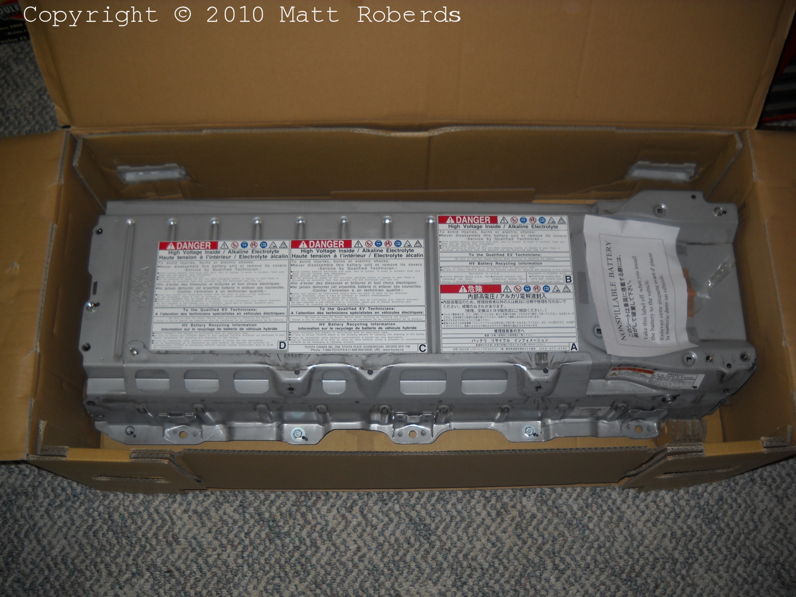
This is what I saw when I opened the box. |
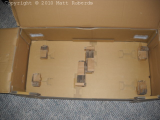 |
And this is the packing material in the bottom of the
box. As far as I can tell, the battery is not strapped in or tied down in
any way; it just sits in the box. |
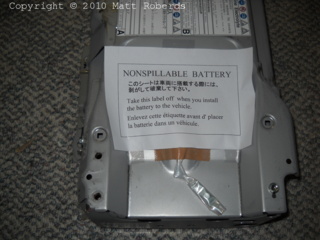 |
The "Nonspillable Battery" label is required for
shipping only. It is held on with office-type clear adhesive tape. More
about the nuts in the bag below. |
 |
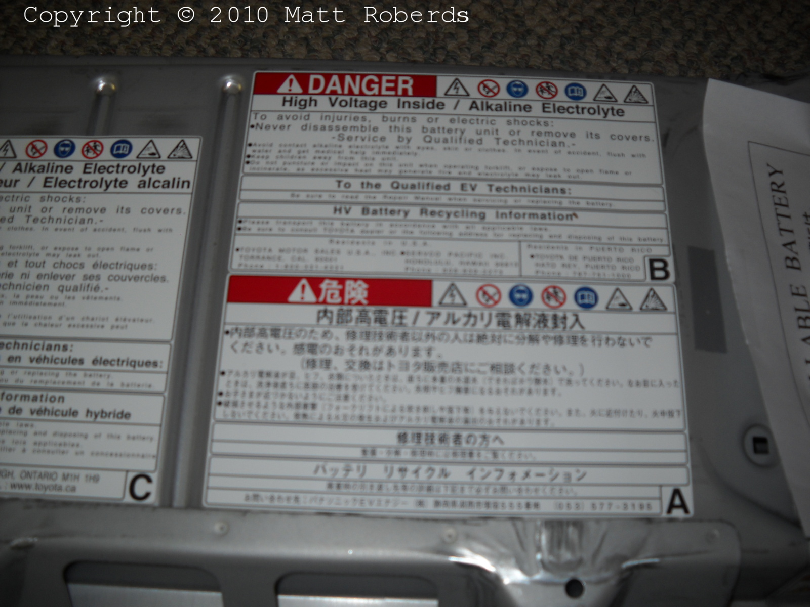
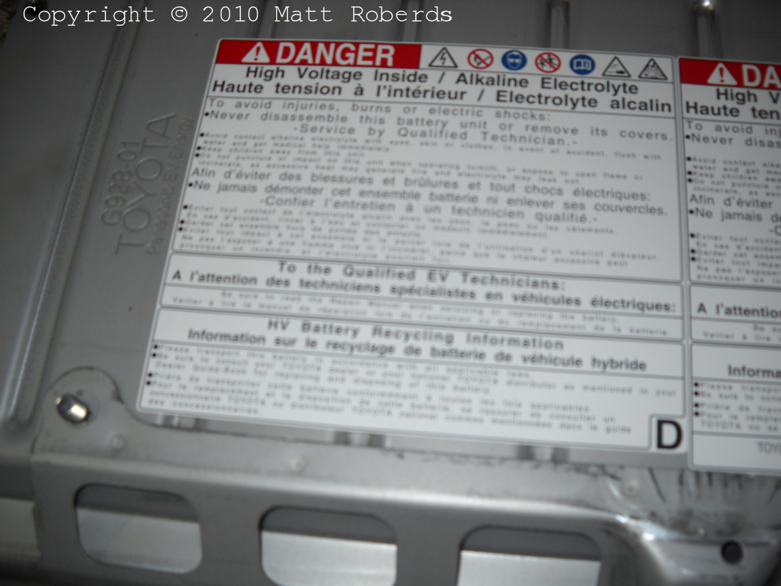
Warning label 1 of 3. This one is in English and
Japanese. The English half has US addresses. |
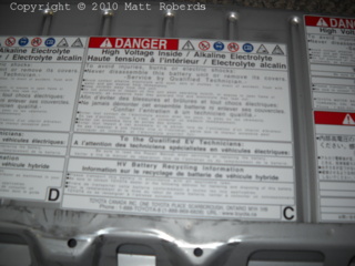 |
Warning label 2 of 3. This one is in English and
French. It has a Canadian address. |
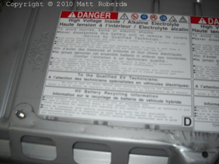 |
Warning label 3 of 3. This one is also in English and
French but it doesn't have an address. |
 |
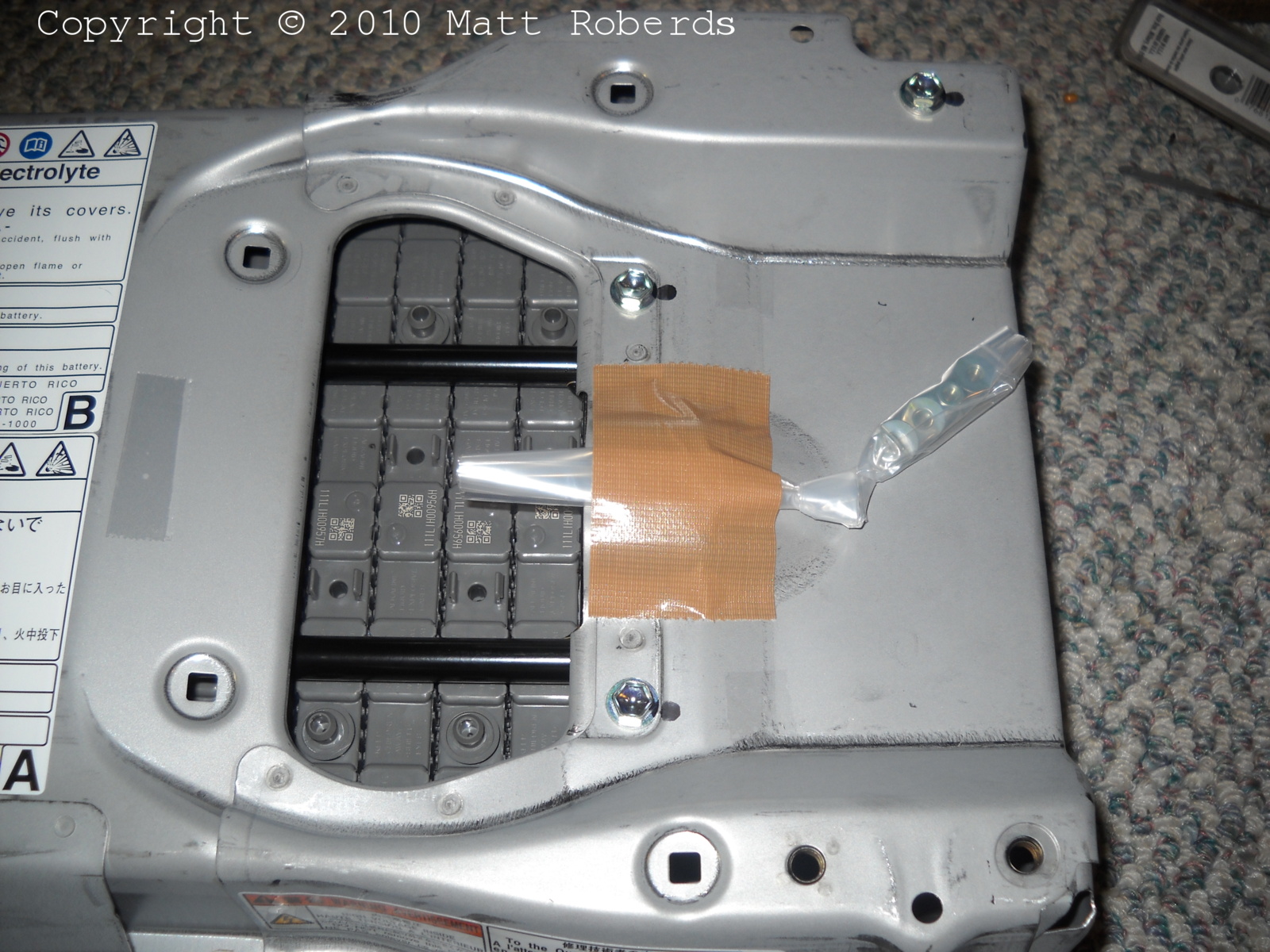
This is what I saw after I removed the "Nonspillable Battery" label.
The plastic bag taped to the battery case contains the four module
terminal nuts that are not already installed - two for the service plug
cables, two for the main cables.
In the car, the big hole is where the blower duct sucks cooling air
out of the battery case. Here, you can see a few of the modules through
the hole.
|
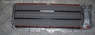 |
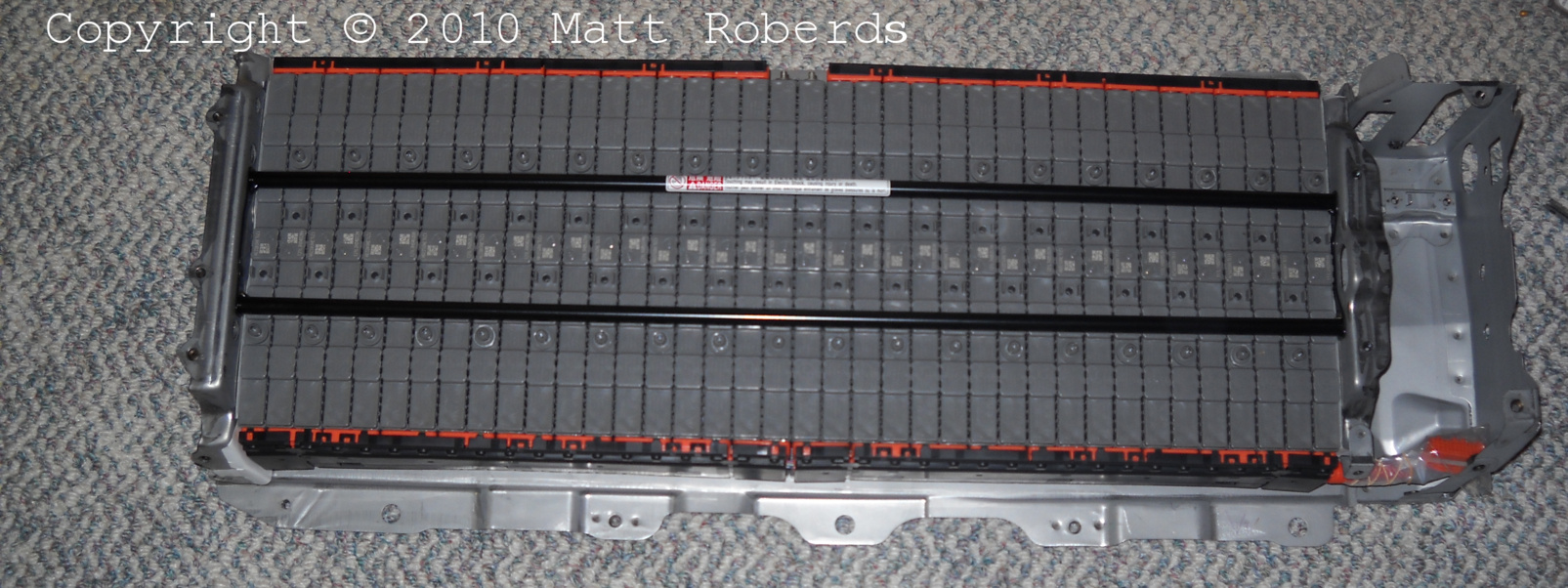
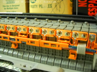
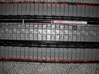
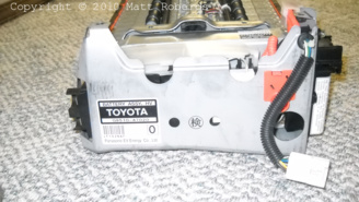
Hey, look, I really did get NiMH modules instead of old pinball machine
parts!
The battery is shipped with the cover bolted on. You have to remove
some 12mm and 10mm nuts, plus one T30 Torx screw, to remove the
cover.
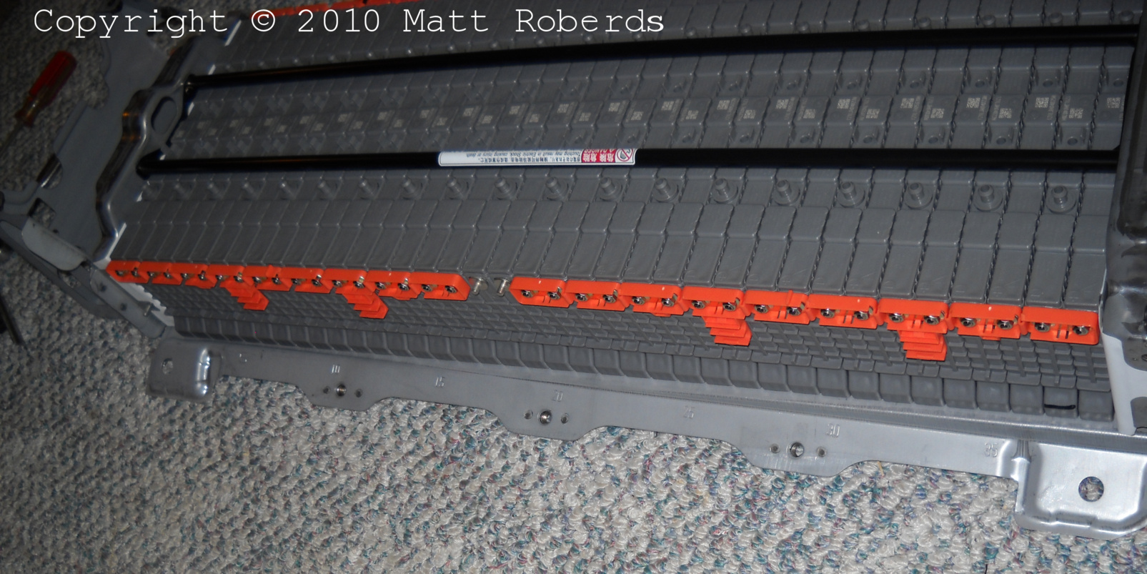
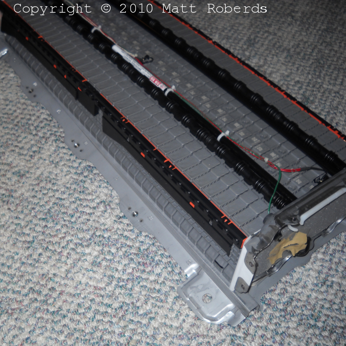
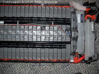
The modules are installed and clamped in. The front and rear bus bar
modules (orange) are already installed and bolted to the module studs.
The sense wire harness is already installed, and the orange connector
for it is in the battery ECU / system main relay compartment, with a
plastic bag over it. The black plastic bus bar module protectors are
already installed on the bus bars.
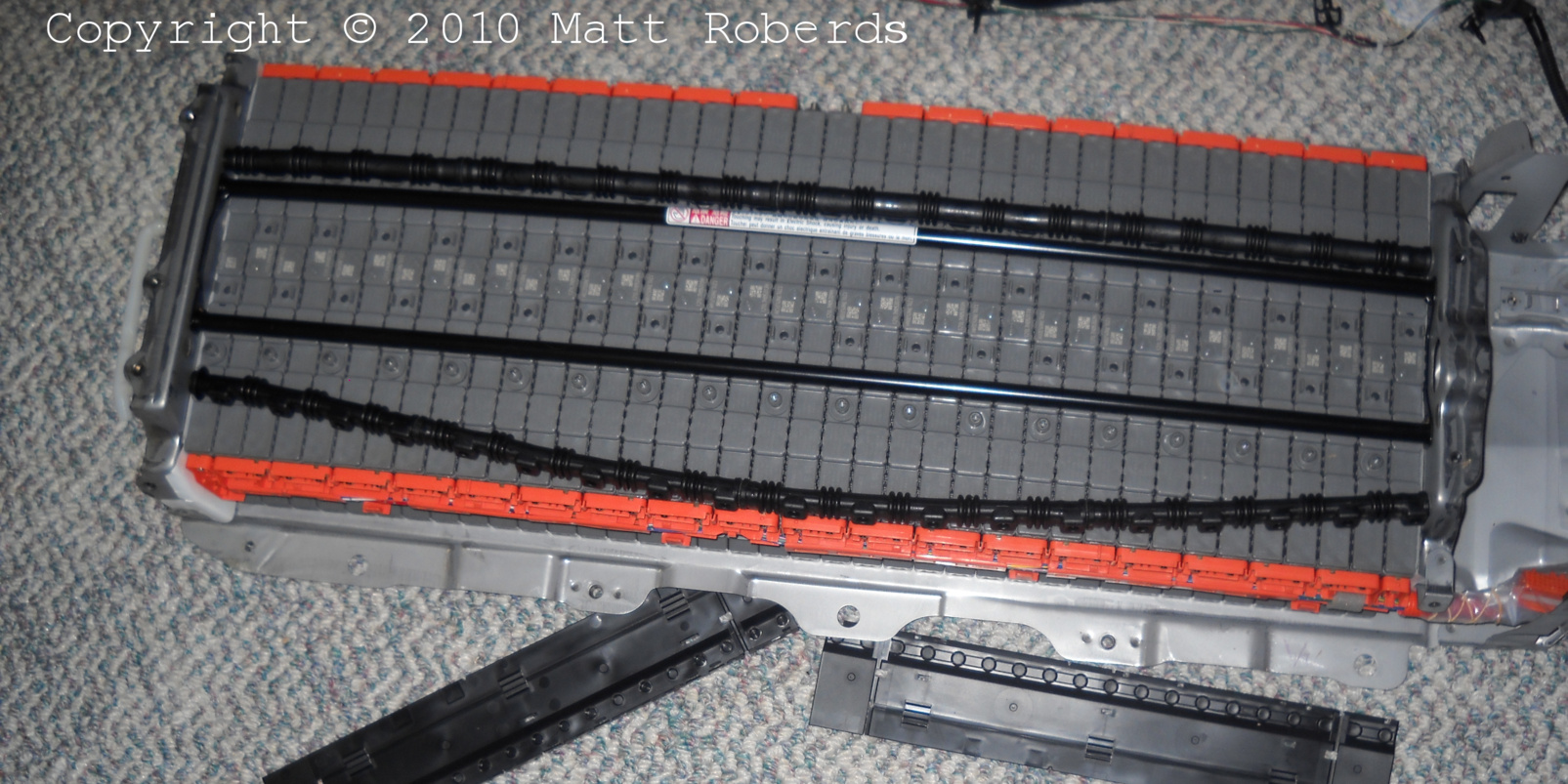
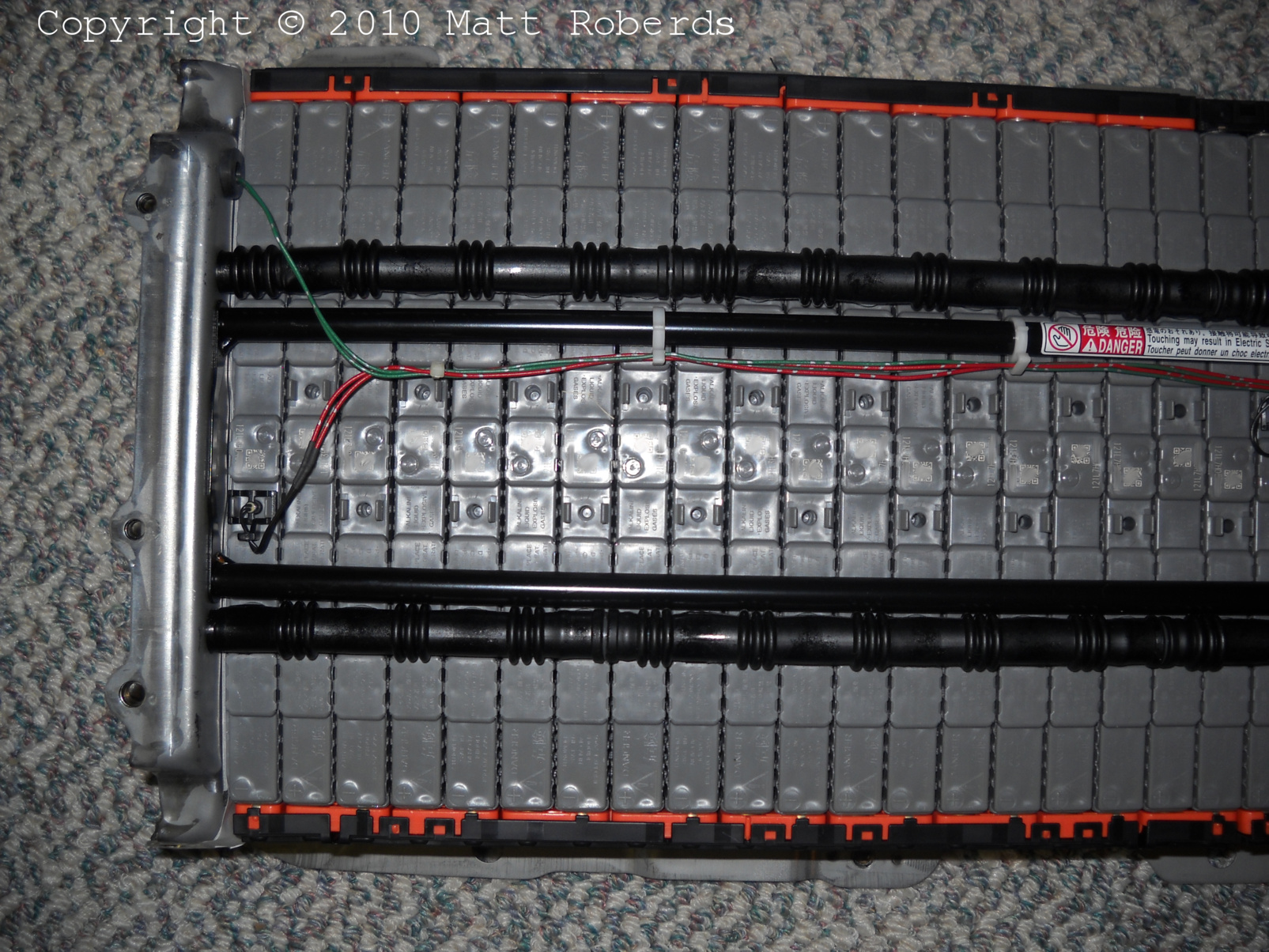
|
 |
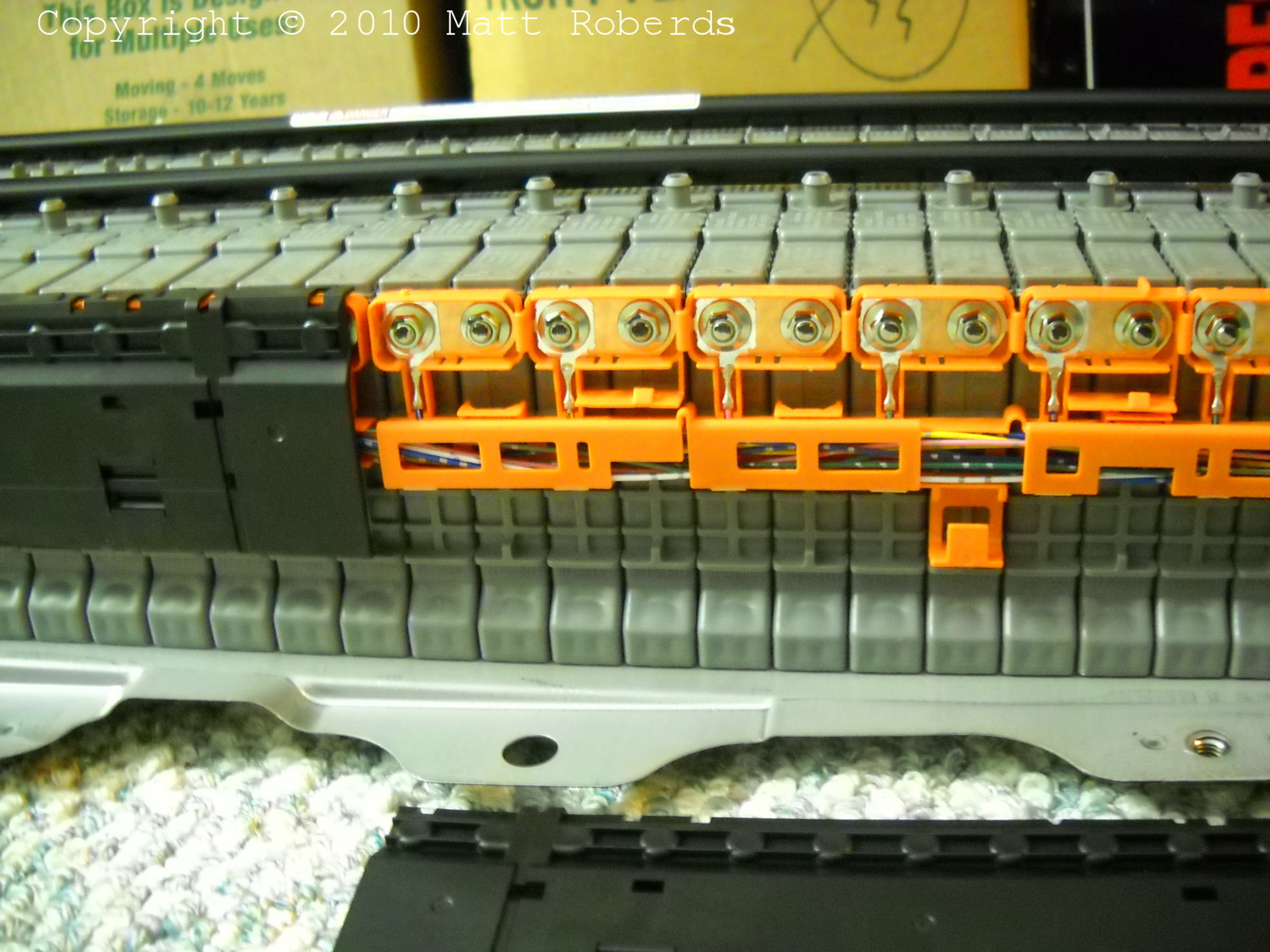
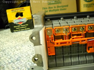
View with one of the bus bar module protectors
removed. Note that the module stud on the far right has no nut on it;
this is where the main cable (positive) bolts on. |
 |
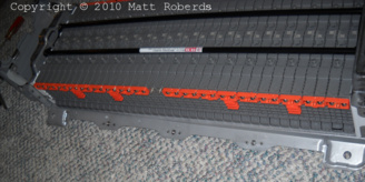
Same as the previous view, but a little further
towards the center of the battery. |
 |
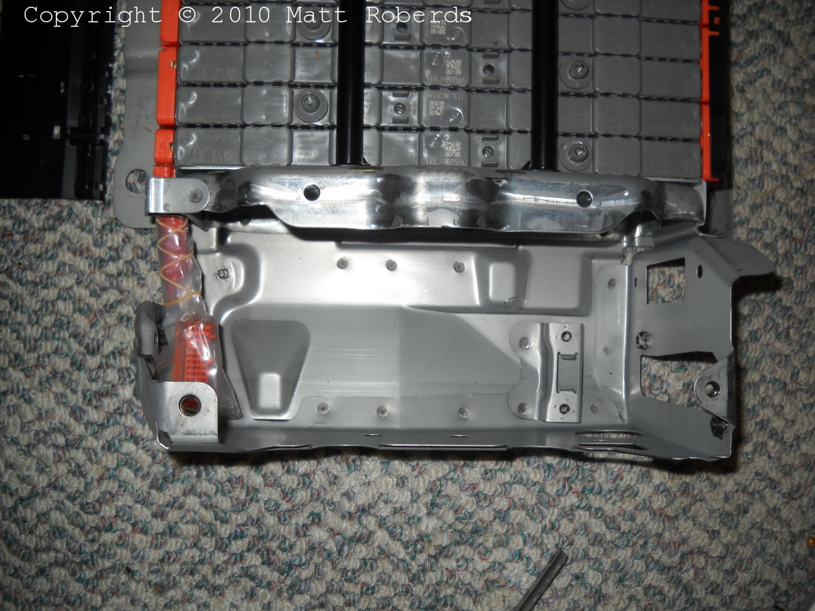
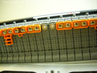
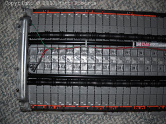
The far end of the battery, with the second bus bar module protector
removed. The module stud on the far left has no nut on it; this is
where the main cable (negative) bolts on.
In the background there is a box full of lubricant for the qualified
EV technician. It is made from renewable natural resources and all
waste products are biodegradable. The containers can also be locally
recycled (into fiberglass insulation). CAUTION: Only for use
after working on batteries, not before.
|
 |
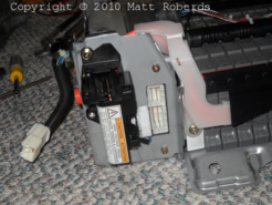
This is where the battery ECU and system main relay
(SMR) go. The orange connector on the left plugs into the battery ECU; it
has a wire to every other module in the stack, so the ECU can monitor the
voltages of every two modules. |
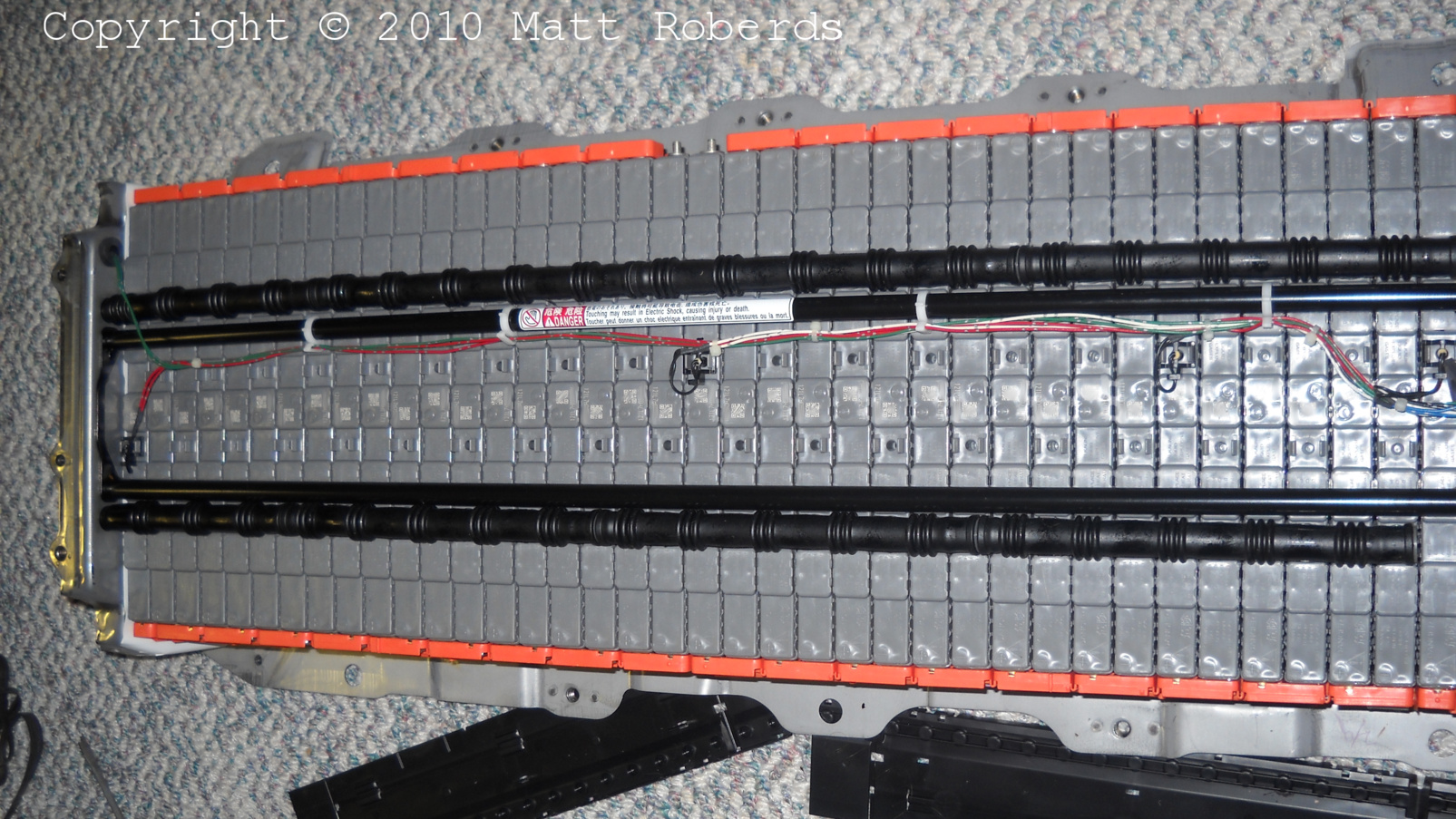
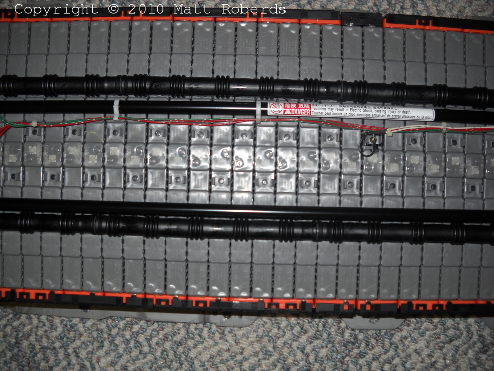
 |
View of the front of the battery with both bus bar
module protectors removed. The two module studs in the center have no
nuts on them; this is where the two cables to the service plug bolt
on. |
 |
Close-up of the two center modules where the service
plug cables connect. There is a black plastic insulator around these
cables that has to be transferred from the old battery. |
 |
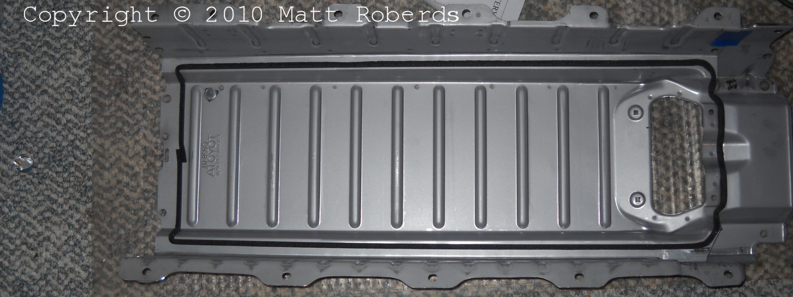
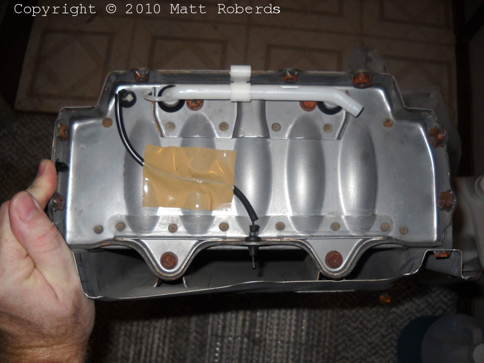
The inside of the cover. The black stuff appears to
be foam weatherstripping. |
 |
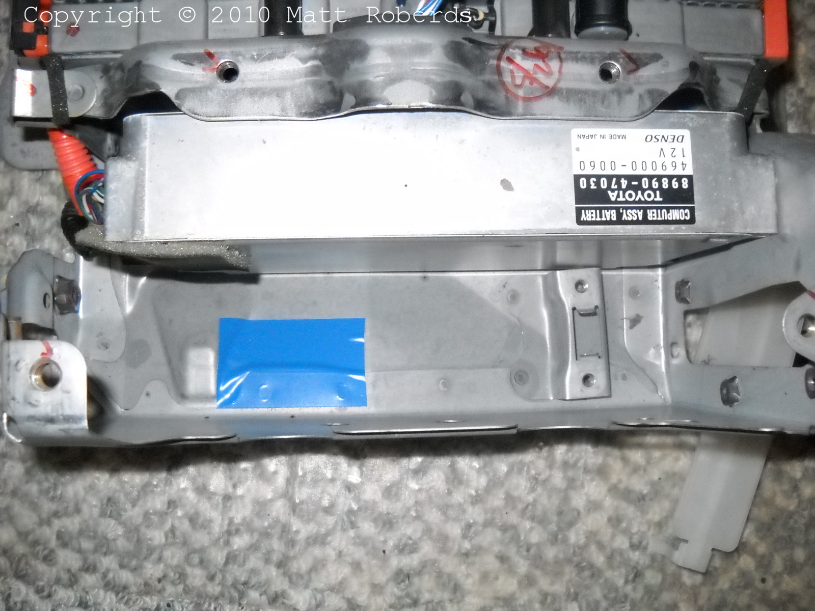
Another view inside the cover. The blue tape
apparently provides some extra protection to a place where several cables
end up. |
 |
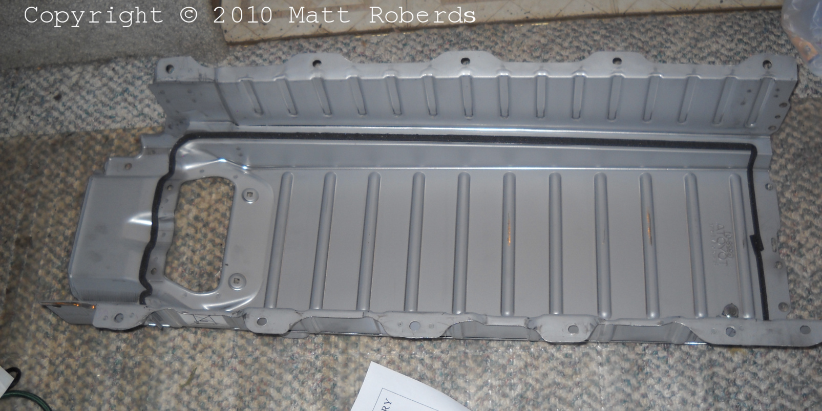
Another view inside the cover. |
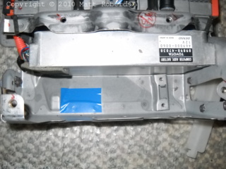
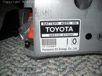 |
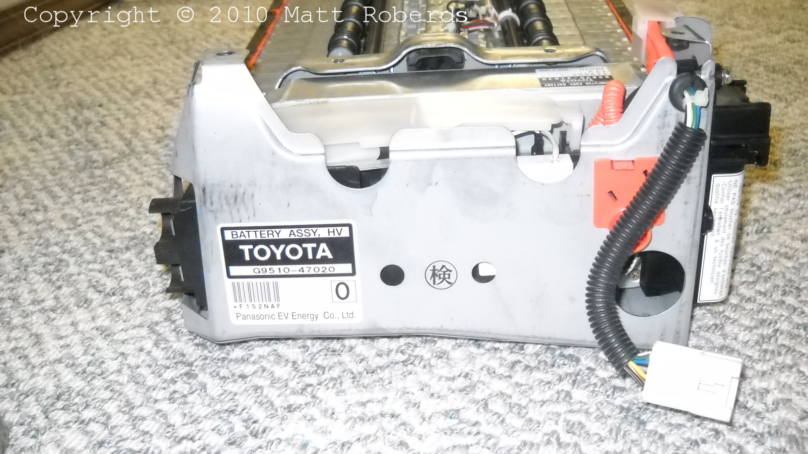
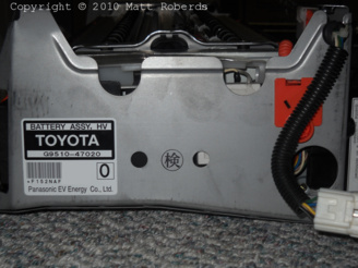
The serial number label on the new battery; partially
edited. |
Getting the old battery out of the car
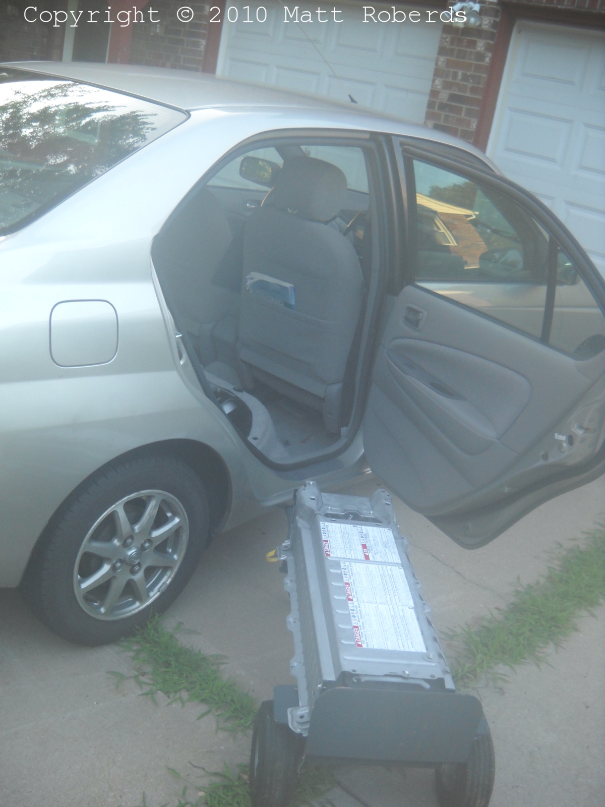
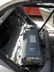 |
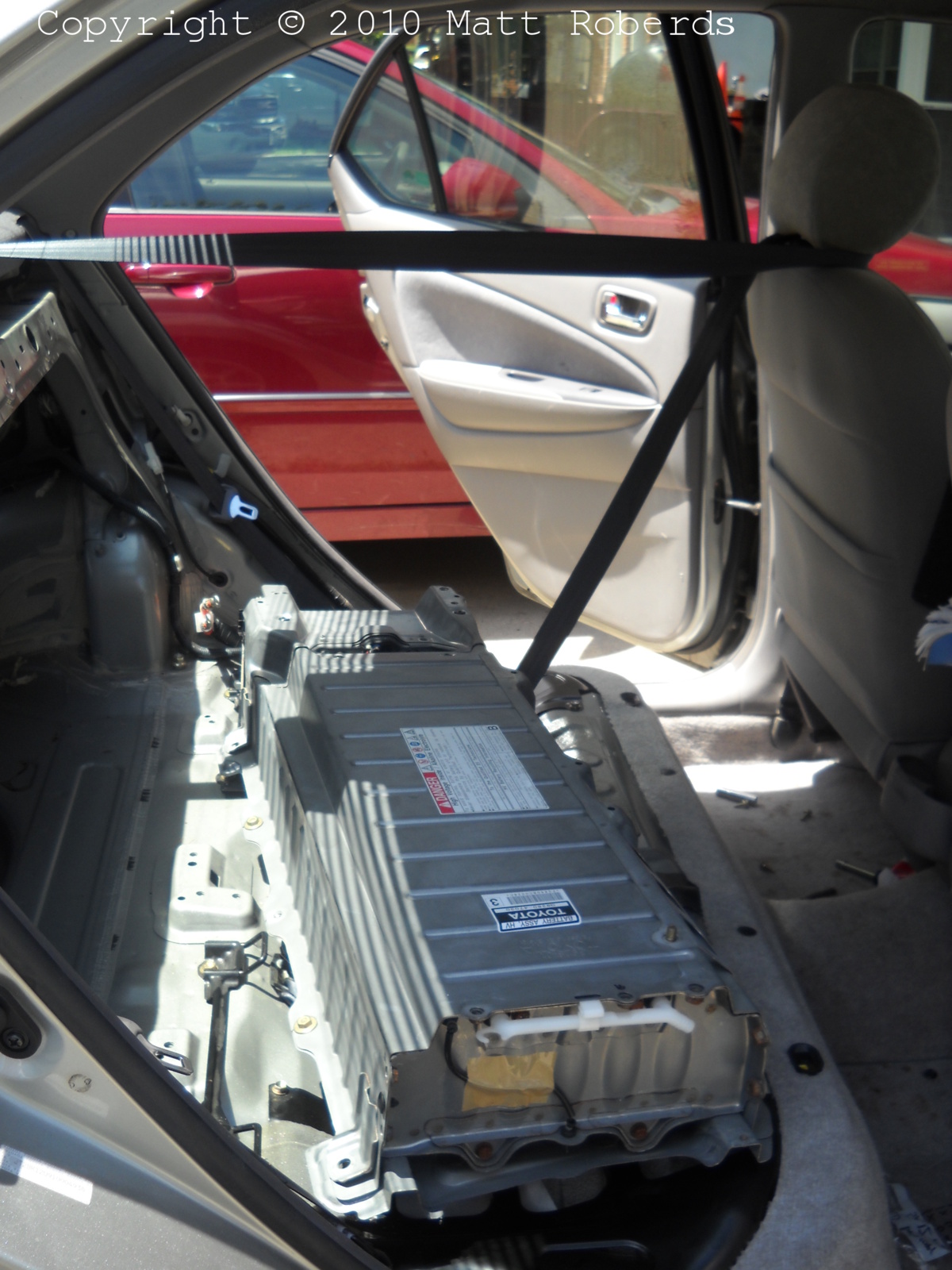
The directions in SSC 40G sort of imply that the battery goes in and
out through the trunk, but I took it out through the rear passenger
door.
At this point I had already lifted the ends of the battery, one at a
time, past the "humps" where the C-pillars meet the trunk floor, and
had it sitting where the bottom cushion of the back seat would normally
be.
I had to take out several bolts to get to this point: the ones that
hold the rear seat back in, the ones that hold a couple of support bars
for the rear seat back, and the ones that hold down the battery itself.
None of them were particularly tricky to get to. I put each bolt or set
of related bolts in a plastic sandwich bag, and labeled the bag with a
felt-tip permanent marker. John Muir taught me to do this and it
works.
|
 |
Another view. I left the seat belt for the center
rear seat passenger installed and just put it around the driver's
headrest to keep it out of the way. |
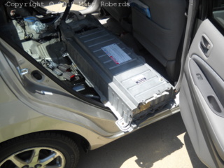 |
Starting to come out the door. Be careful, or the
flange of the battery can cut the door gasket. It is also not hard to
scratch the inner door panel with the battery. |
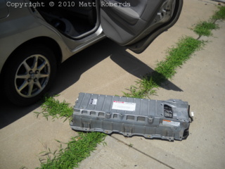 |
On the ground, next to the car. (I was by myself, so I couldn't take
photos between the above one and this one.)
Note that in this photo, I have turned the battery almost 180
degrees from the way it sits in the car. Normally, the end with the big
hole in the top cover is on the driver's side.
|
 |
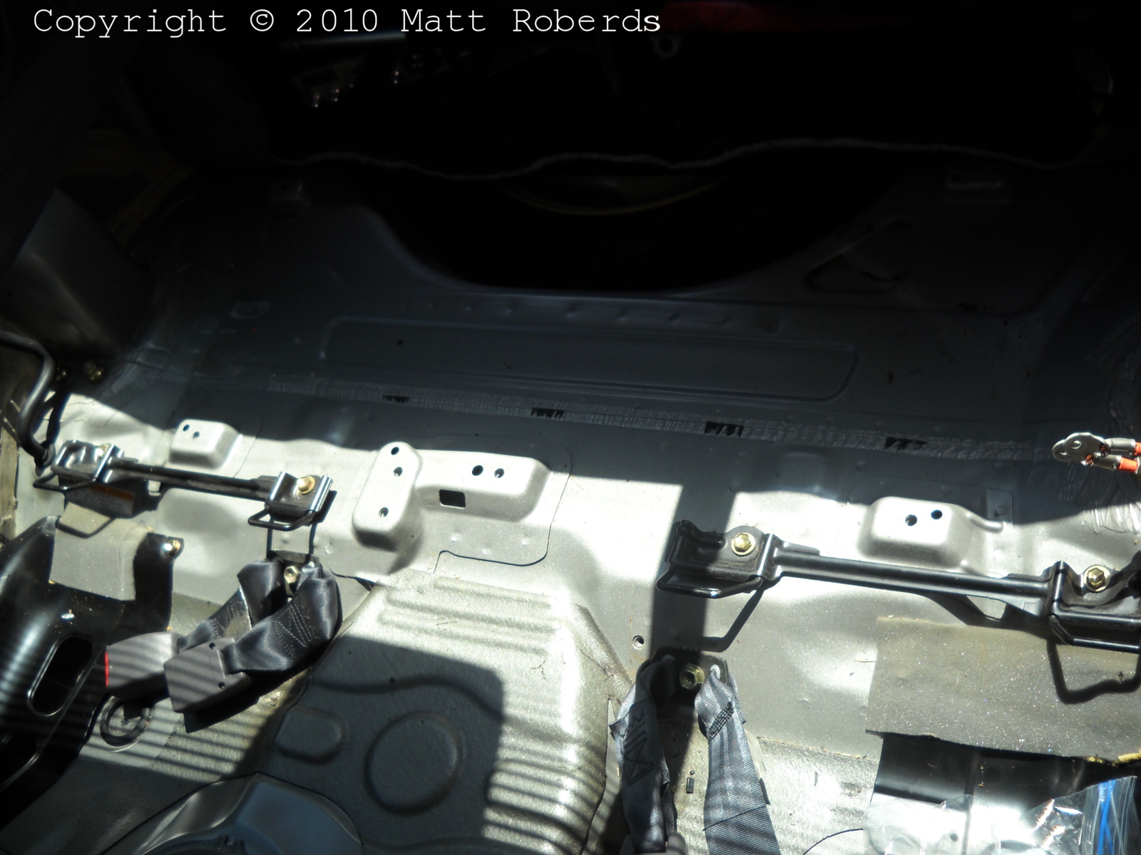
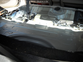
Standing outside the rear driver's-side door, looking
back into the trunk at where the battery used to be. You can see the two
main cables at the far right side of the picture. The three places where
the front edge of the battery bolts down to the floor are also visible,
just forward of the shadow of the rear parcel shelf. |
 |
Standing behind the car, looking forward into the
trunk at where the battery used to be. You can see the two main cables at
the far left side of the picture. One of the places where the rear edge
of the battery bolts down to the floor is also visible, at the lower
right corner of the photo. |
 |
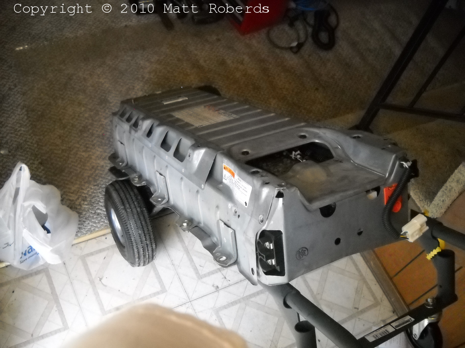
Moving the old battery into the house on a hand truck
(dolly, two-wheeler). I first stood the battery on end, then walked it
onto the hand truck. This is a relatively convenient way to move the
battery around. Since I only had to go about 30 feet (10 m) on the level,
I didn't strap the battery to the hand truck; if I needed to go up or
down steps, a strap would have been a good idea. |
Stripping the old battery
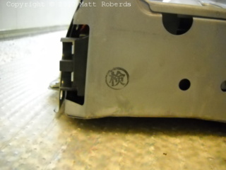 |
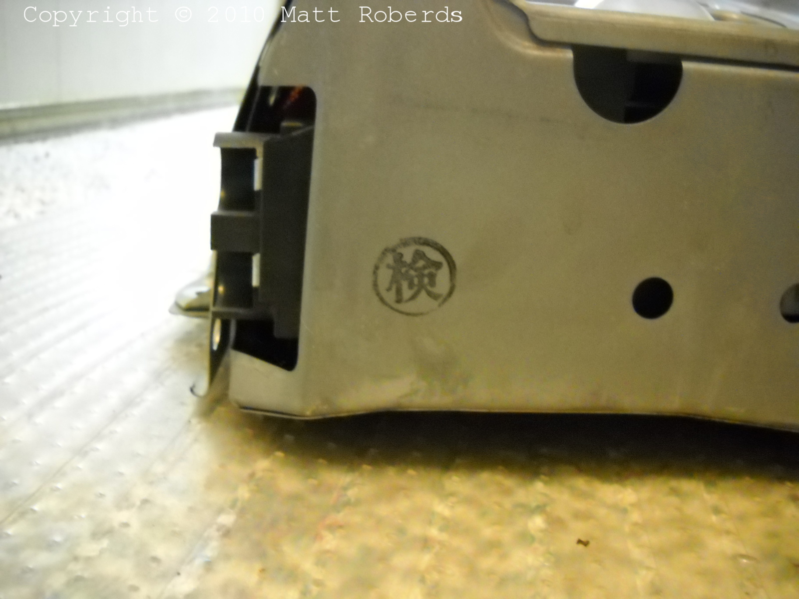
This says "Kilroy was here." I really think so. |
 |
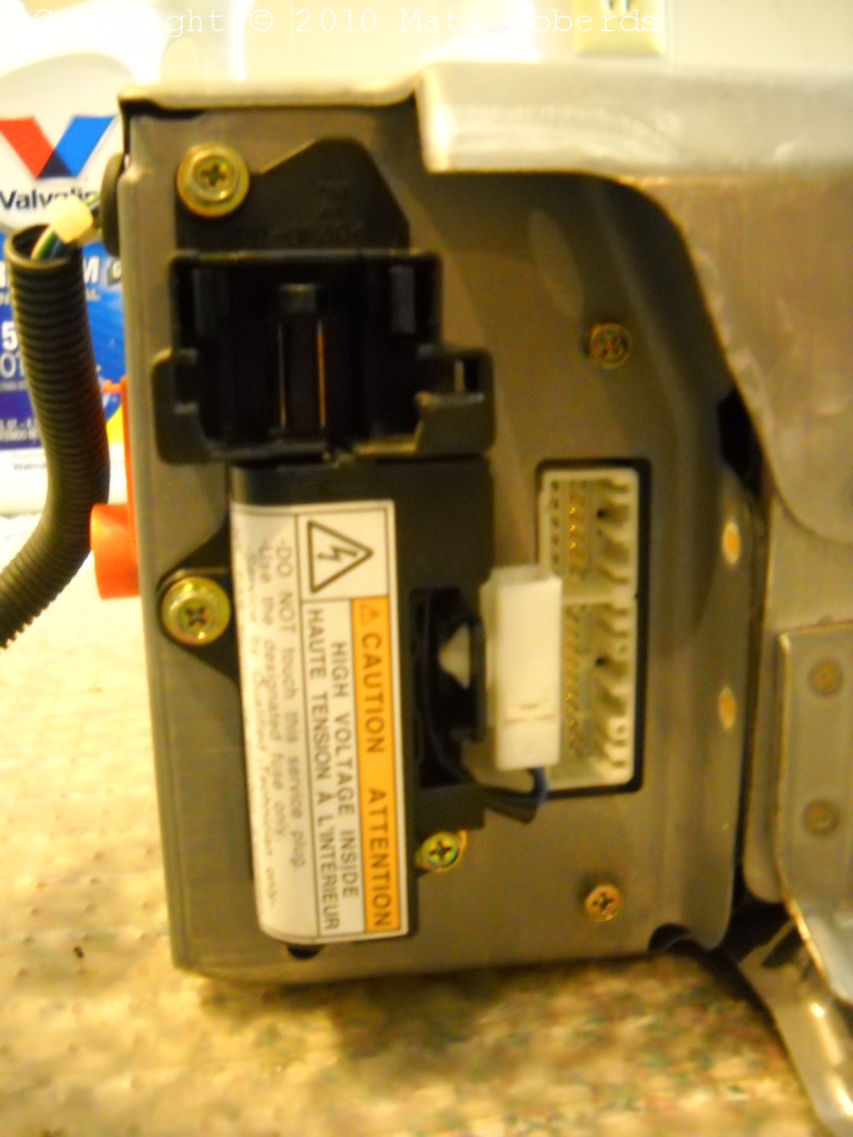
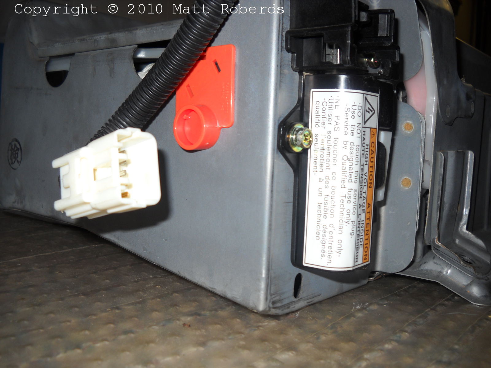
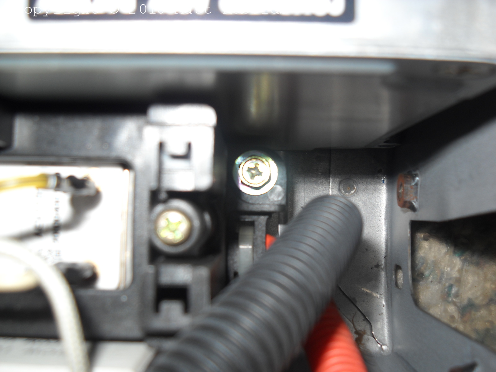
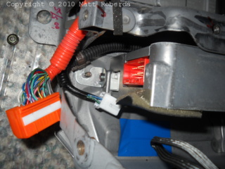
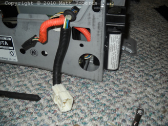
This is the external part of the service plug assembly. Note that it is
held to the case with three screws. The vertical white connector is for
the microswitch that detects whether the service plug is locked in.
The white connector visible through a hole in the battery case is
the battery ECU connector. There is one screw above and one screw below
this connector; these hold this end of the battery ECU to the battery
case.
|
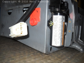 |
Another view of the service plug. The white connector
hanging at the left of the picture is for the SMR. The orange plate on
the end of the battery holds the secret charging connector; more
below. |
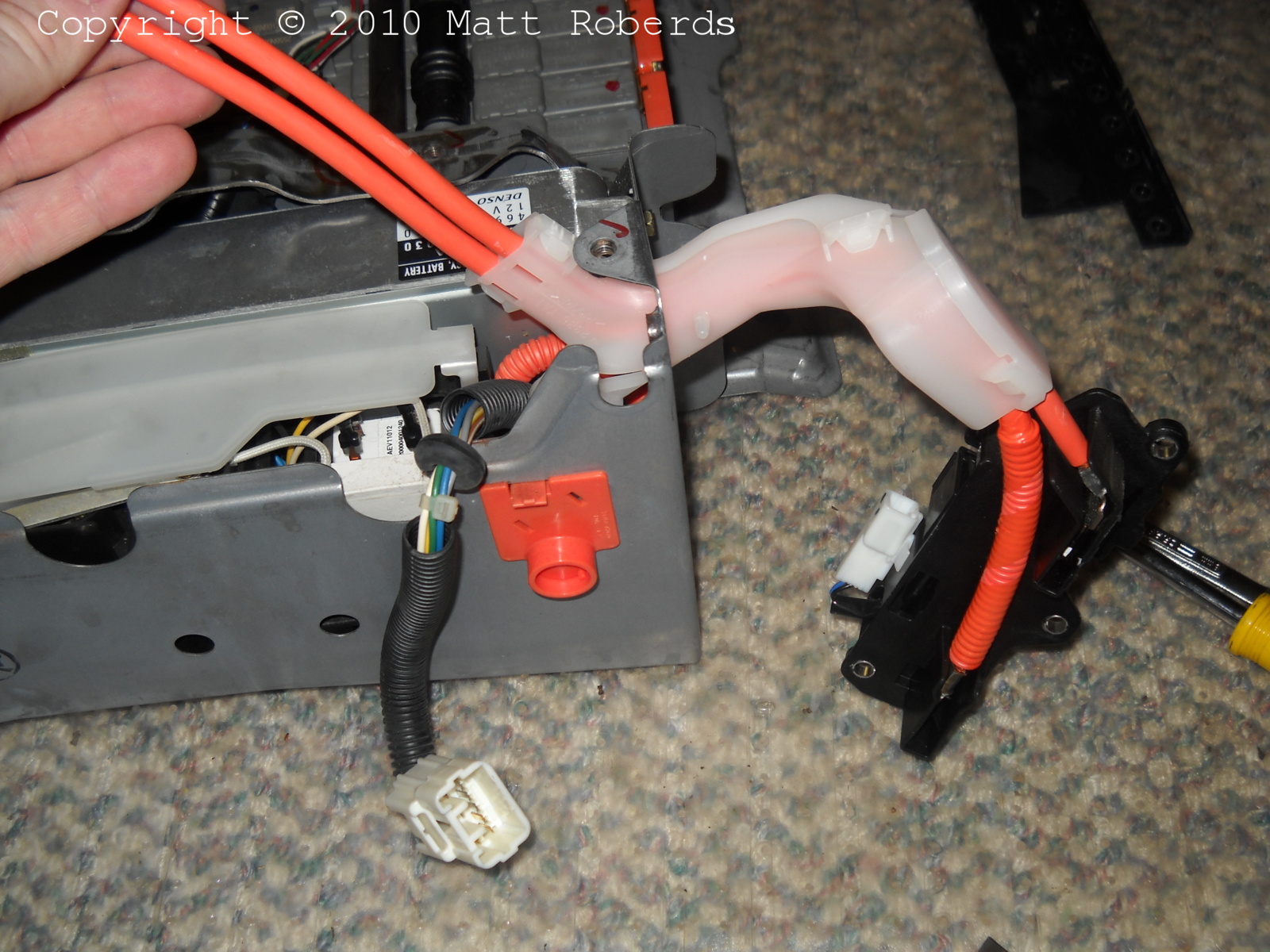
 |
Looking at the end of the battery on the passenger side. At the top,
the white plastic pipe is the vent manifold that connects the two
rubber vent tubes from the modules to the vent tube that goes overboard
in the car.
The wires that run from the top left to the bottom center go to the
thermistor that senses the battery intake air temperature. These wires
are part of the thermistor harness that runs on top of the modules
inside the battery. The wires are taped to the battery case.
|
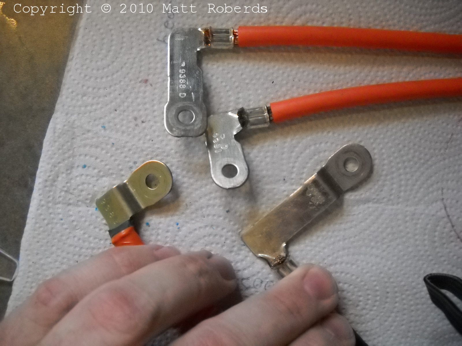
 |
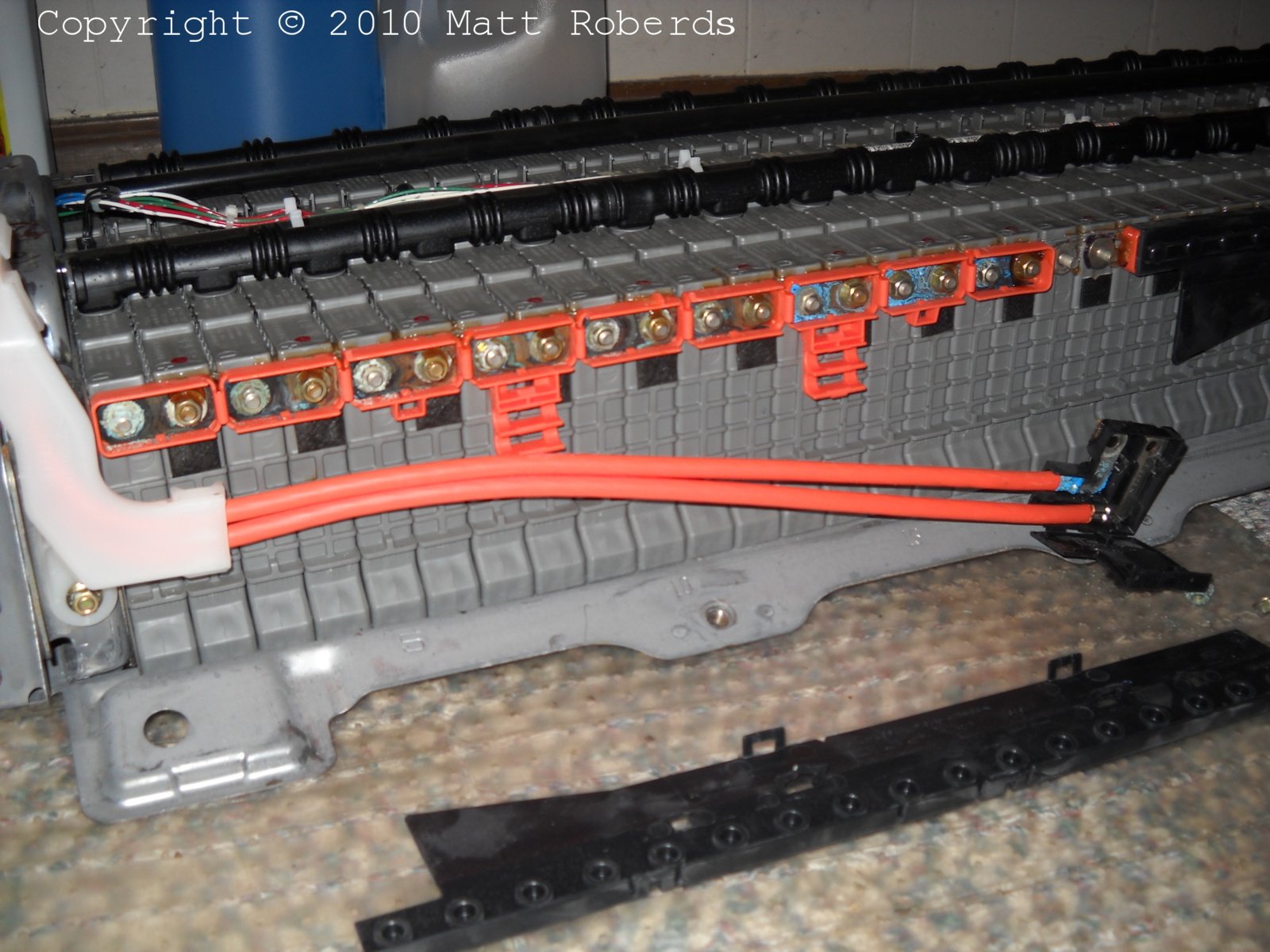
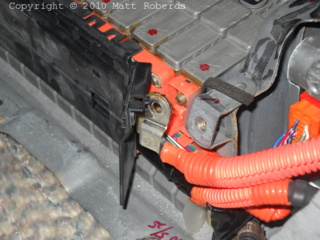
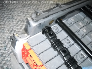
Two nuts removed and two cables to the service plug, complete with
black plastic insulator, removed from the center modules. Normally the
thick orange cables are each clipped into the two orange clips that
hang down from the bus bar modules.
This battery had SSC 40G done to it, as can be seen by the sealing
goop on every other module stud, as well as by the black squares below
every other module stud.
|
 |
One nut removed and one main cable (positive) removed from the end
module. Its insulator stays with the bus bar module.
Not pictured: the other end of this cable connects to the top of the
SMR with a screw.
|
 |
One nut removed and the other main cable (negative) removed from the
end module. Its insulator stays with the bus bar module. Normally the
thick black cable is clipped into the orange clip that hangs down from
the bus bar module.
Not pictured: the other end of this cable connects to the top of the
SMR with a screw. There is also an "aluminum shield" on this cable that
is screwed down to the battery case near the battery ECU / SMR
compartment.
|
 |
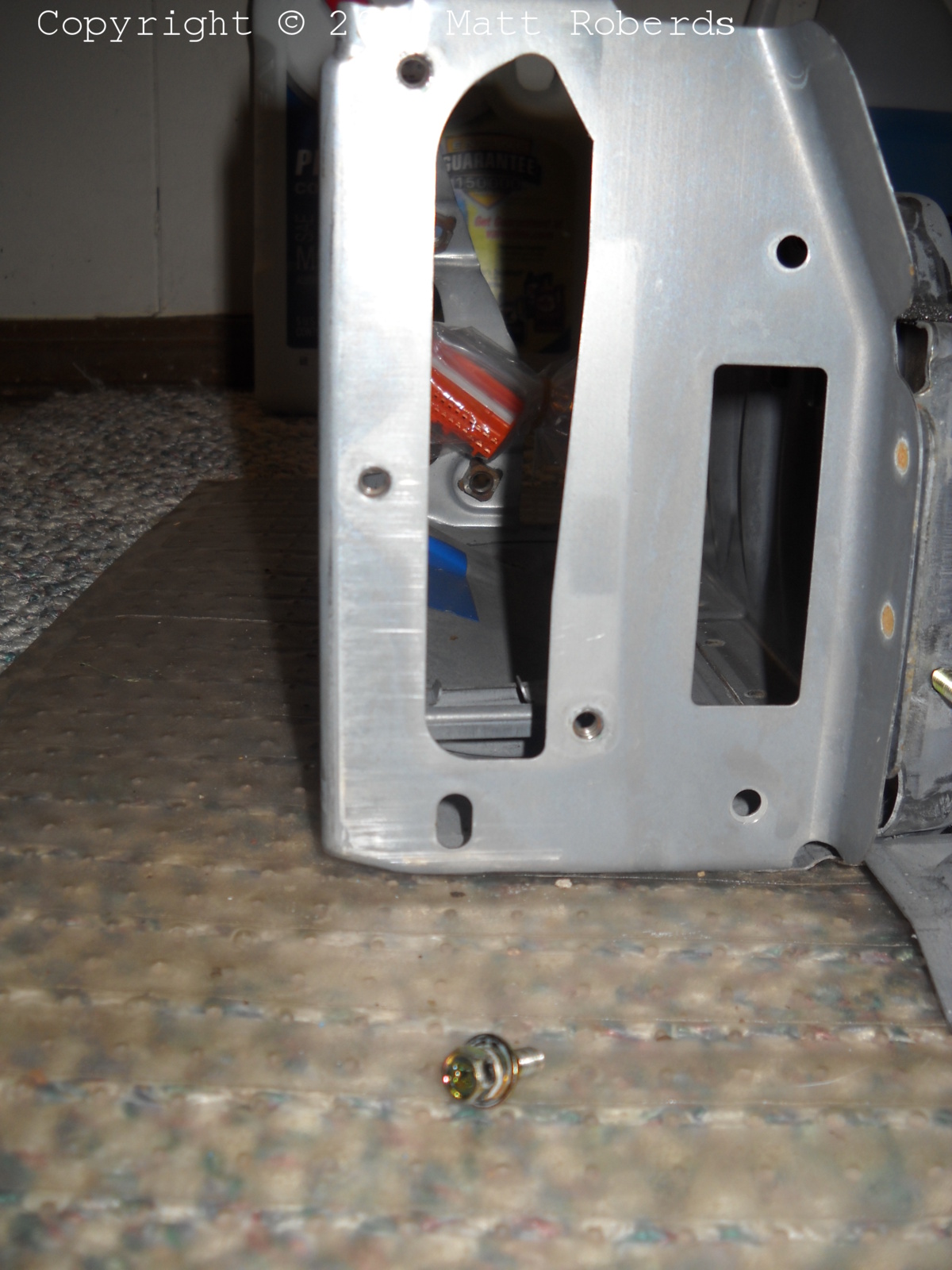
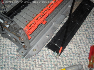
SSC 40G implies that the cables can be detached from the back of the
service plug assembly, but doesn't specify exactly how. I looked at the
connections and I am not sure how they come apart; they might
join together kind of like sticking a knife between the tines of a
fork. I decided to see if I could remove the service plug assembly
without detaching the cables.
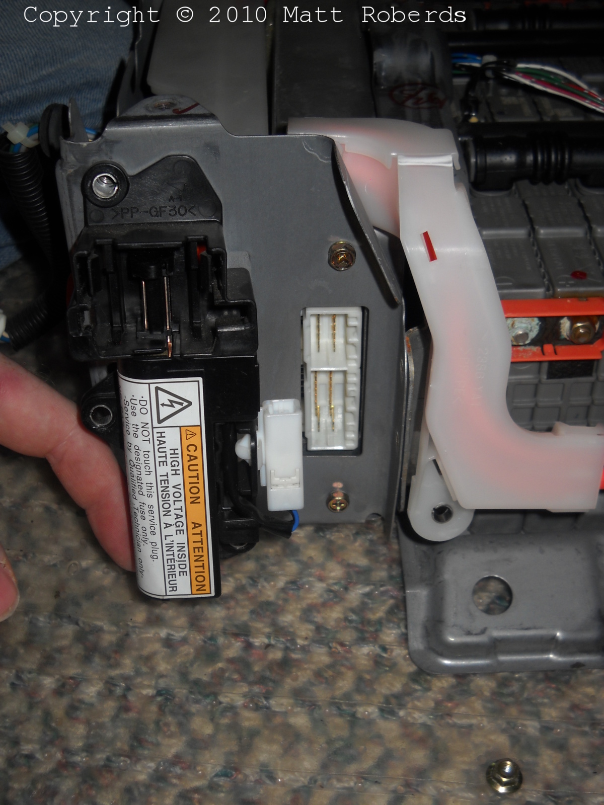
The white plastic cable protector, on the right, is held to the case
by a nut at the bottom (seen removed at the bottom right of the photo).
Once that nut is removed, and all three screws that hold the service
plug assembly to the case are removed, I could swing the bottom of the
service plug assembly up, as if it were hinged at the top of the
battery case, and then start feeding the white plastic cable protector
through the hole in the battery case.
|
 |
A little further along in service plug assembly
extrication. At this point I removed the secret charging plug to gain a
little more room. |
 |
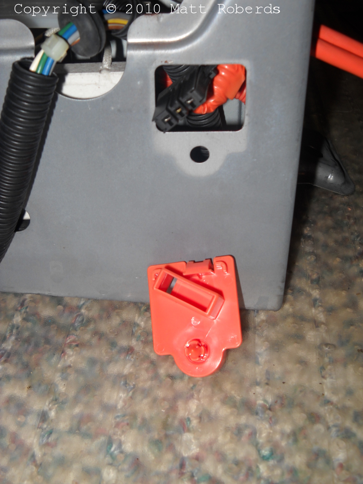
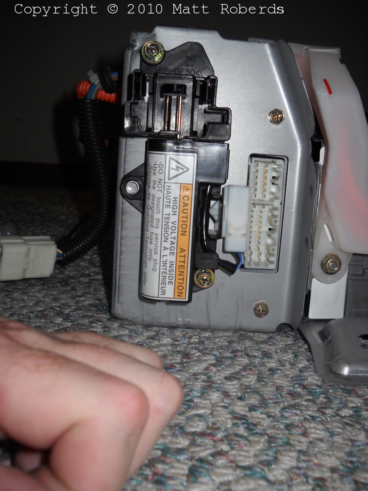
This orange plastic plate is clipped to the side of the case with an
"interlock" plug, just like the one on the cover for the main cables
inside the car. Unclipping the interlock plug let me remove the plate
from the side of the battery case.
Once I did that, I found the secret charging plug clipped into a
cavity on the back side of the plate. This plug has a wire to the most
negative module, a wire to the most positive module, and a wire to what
I assume is 12 volt ground. The connection to the modules goes through
a fuse on the bottom of the SMR.
I suspect, but don't know, that this plug is used at the
factory and maybe at the warehouses to check on the overall battery
voltage and possibly to recharge it, using a very well-regulated
charger with overcurrent, overvoltage, and timed shutoffs.
Anyway, once I got this out of the way, I could get the service plug
cables fully out of the battery case.
|
 |
Looking down into the SMR compartment to see one of
the three mounting screws for the SMR... |
 |
...and the second mounting screw about an inch (2.5
cm) away. These are fairly far down there; I used a nutdriver to loosen
the screws, and then magnet-on-a-stick to get them out. |
 |
There is a third SMR mounting screw on the front
(FRONT) of the battery case. Once it is removed, I could lift the rear
end of the SMR up, and lift the SMR out of the battery case. |
 |
The hole where the SMR was. |
 |
The sense wire harness (orange plug) unplugs from the
ECU first. Then, the thermistor harness (white plug) can be unplugged.
Then, I could remove the nut that holds the "foot" bracket for the front
edge of the battery ECU. I removed the two screws near the battery ECU
connector at the rear of the battery case (seen above) and the battery
ECU lifts out. |
Removing the vent tubes (not shown)
My vent tubes were sticky to the
touch on the outside. As soon as I felt the stickiness, I quickly washed off
my fingers, fearing that there was battery electrolyte on the outside of the
tubes; I did not develop any burns or discomfort on my fingers. I wore gloves
for removing and reinstalling the tubes after that.
Removing the vent tubes was not too hard; basically I grabbed the black
rubber tube with two fingers, and rocked it front to back while pulling up,
to release it from the barb on the module vent tube. Every few modules, I
could feel a hard plastic connector that joins two sections of the rubber
vent tubes; I just left these connected. One of the rubber vent tube
assemblies is slightly longer than the other one.
At the passenger end of the battery, there is a white plastic manifold
that connects the ends of the two rubber tubes. I rocked the manifold up and
down while pulling out on it to release the barbs on the manifold from the
rubber tubes. Once the manifold is removed, I could squeeze in on the rubber
lip at the end of the vent tube, and pull it out of the steel end plate of
the battery.
Removing the thermistor harness (not shown)
I did not have to
cut off any thermistors or connectors! The holes that everything has to go
through are big enough to fit what has to go through it.
I started by removing the intake air temperature thermistor, seen above.
It is held in by a rubber grommet through the sheet metal - I squeezed the
grommet and worked it out of the sheet metal, being careful of the exposed
thermistor. I peeled back the tape on the end of the battery, and removed the
rubber grommet through the steel end plate by squeezing and pulling. I then
carefully pulled the wires and thermistor towards the interior of the
battery.
Next, I noted which modules on the old battery had thermistors on them,
and marked the modules on the new battery that should have them. (I used a
felt-tip permanent marker.) I also noted where the four white plastic clips
are that hold the harness to the strut. I worked my way from the passenger
side to the driver's side, unclipping the thermistors and pulling them
straight up out of the modules, and unclipping the white plastic clips from
the strut.
At the battery ECU compartment, I squeezed the rubber grommet and pushed
it out of the sheet metal - from the battery ECU compartment towards the
modules. Once the grommet was free, the hole in the sheet metal was big
enough to pass the connector through.
Removing the plastic nuts for the air duct
The driver's side air duct
attaches to the top cover with sheet-metal screws into four plastic nuts that
are pressed into the top cover. The new battery does not come with the
plastic nuts.
I used a pair of pliers to gently squeeze the plastic nuts and push them
out from the inside of the old battery cover towards the outside. Each nut
also has a tiny rubber gasket under the head, which sometimes stayed with the
nut and sometimes stuck to the cover. I peeled off the gaskets that were
stuck to the cover and reinstalled them on the nuts.
Then, I used my fingers to push the nuts into the new battery cover.
Additional photos
You can see some more photos of the System Main Relay (SMR) and the
service plug assembly on the Components
page.
Cleaning the cables
The ends of the main cables and service plug cables that bolted to the
modules had some corrosion on them; mostly blue flaky stuff. I wanted to
clean this corrosion off before putting the cables on the new battery. It is
also possible for these cables to have a little alkaline electrolyte on them
and I wanted to clean that up too. I soaked the cable ends in vinegar (the
bottle says "distilled white vinegar, diluted to 5% acidity"), and when they
quit bubbling, I took them out and rinsed them in tap water. I scraped off
the remaining gunk with a plastic scraper, then used more vinegar and tap
water. Finally I used a kitchen sponge (mostly soft yellow foam on one side,
but with a thin green scrubbing pad on the other side) to shine up the ends
of the cables, followed by a final rinse and drying with paper towels.
 |
These are the service plug cables. I put just enough
vinegar in the bottom of the cup to cover the cable ends, and then let
the ends soak in it. I was trying to avoid having a lot of moisture get
up between the wire and the cable insulation, and I think I
succeeded. |
 |
Service plug cables soaking. SST QT-32OZ can be
obtained from Mr. Lamar, Tulsa, Oklahoma. :) |
 |
All four cable ends after vinegar and scraping but
before scrubbing pad. |
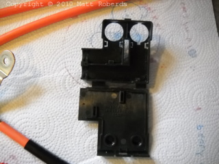 |
This insulator goes around the service plug cable
ends at the modules. The end with the two large holes in it goes under
the cable terminals, and then the end without the holes in it folds up to
cover the terminals. The insulator had some flakes of corrosion from the
cable ends, plus some of the goop installed with SSC 40G on it. I soaked
the whole insulator in vinegar, used a plastic scraper to get rid of the
goop, and then rinsed with water. This shows the insulator after
cleaning. |
Putting parts on the new battery
 |
Second vent tube about to be reinstalled. I put the
tube through the end plate first, and then plugged the vent tube on to
the module closest to the end wall. It took two fingers and a rocking
motion to get it over the barb on the module. Then, I worked my way back
towards the battery ECU compartment. When I had the tube plugged on to
all the modules, I went along the tube again, giving it another push at
each module to get it seated down really well to the top of the
module. |
 |
First vent tube installed, second vent tube ready to
install. |
 |
Both vent tubes on. Thermistor harness installed. I
started by passing the battery ECU connector through from the module
compartment to the battery ECU compartment, and getting the grommet
installed properly in the sheet metal. I then plugged the thermistor into
the module next to the battery ECU, and then worked my way towards the
passenger side, installing thermistors and wire clips as I went. |
 |
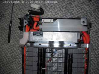
Battery ECU installed, SMR installed, main cables
installed, service plug installed. |
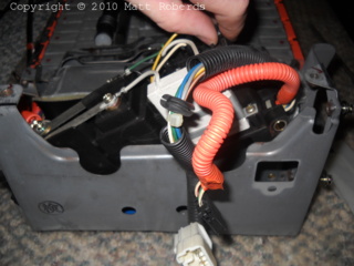
 |
View of battery ECU and SMR compartment. |
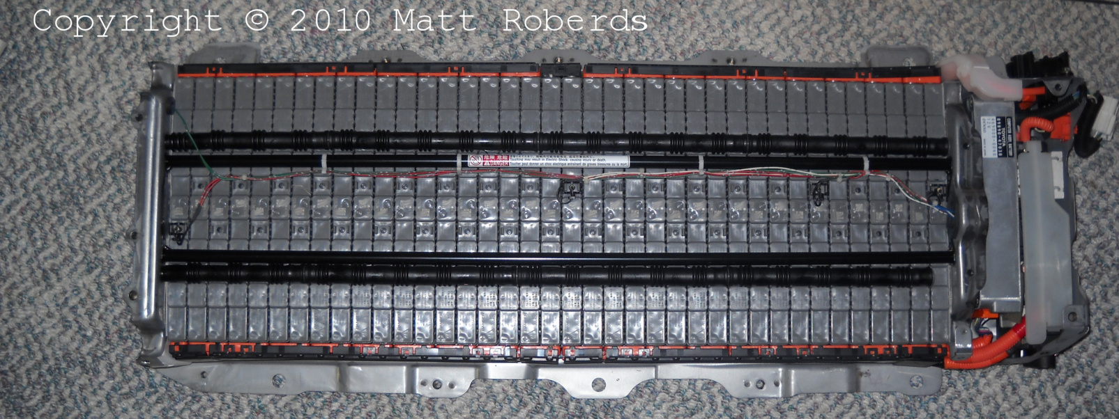
 |
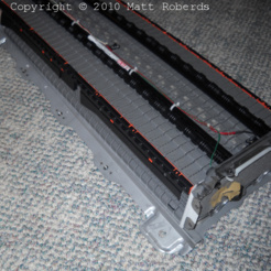
View of entire pack, 1 of 3. |
 |
View of entire pack, 2 of 3. |
 |
View of entire pack, 3 of 3. |
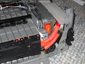 |
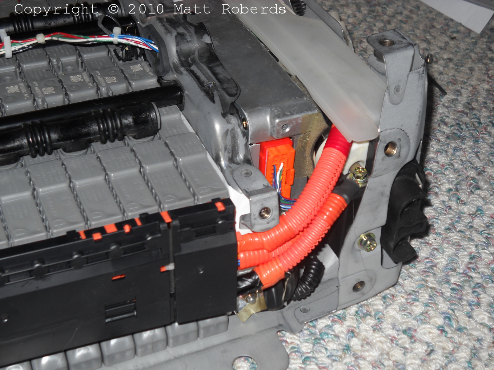
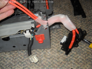
View of cables at front driver's side of battery. The
area where the cables in the orange conduit cross into the battery ECU /
SMR compartment is where the blue tape is on the top cover of the
battery. |
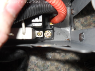
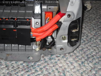 |
View of cables at front driver's side of battery. You
can see the nut that holds the "aluminum shield" for the negative battery
cable onto its stud. |
 |
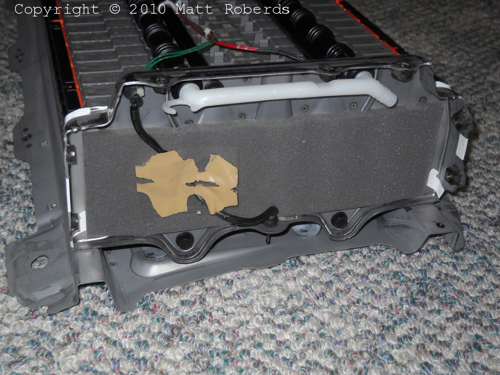
View of passenger end of battery. The new battery has
a piece of foam on the end plate that the old one didn't have. There is a
diagonal slit in the foam, I think for the thermistor wire, but I am not
sure. I re-used the tape from the old battery to hold the thermistor wire
into the slit in the foam. |
 |
View of passenger end of battery. |
 |
View of passenger end of battery. |
 |
View of service plug and battery ECU connector. |
 |
View of driver's end of battery. |
 |
Kilroy was here, too! |
Differences between old and new battery
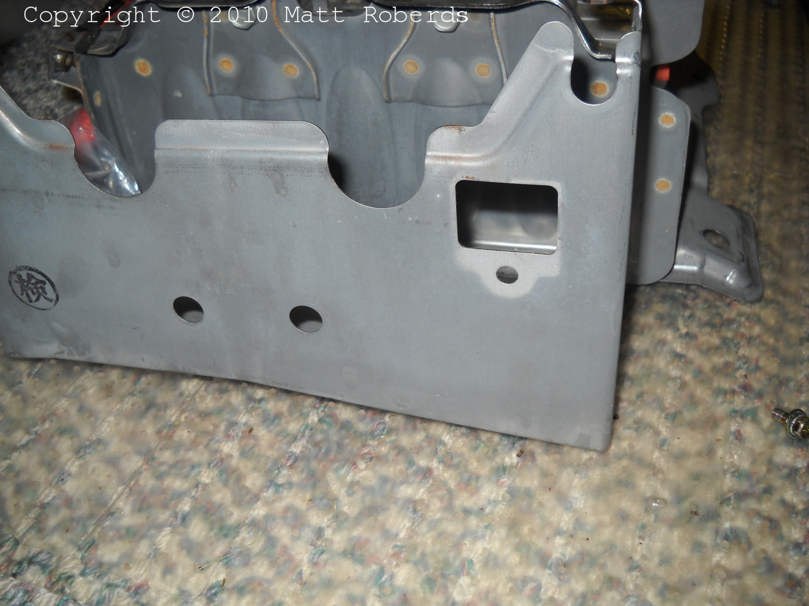
 |
This is where the service plug assembly went on the
old battery - the vertical slot on the left side. There are three
threaded holes: one on the bottom right, one on the center left, and one
on the top left. |
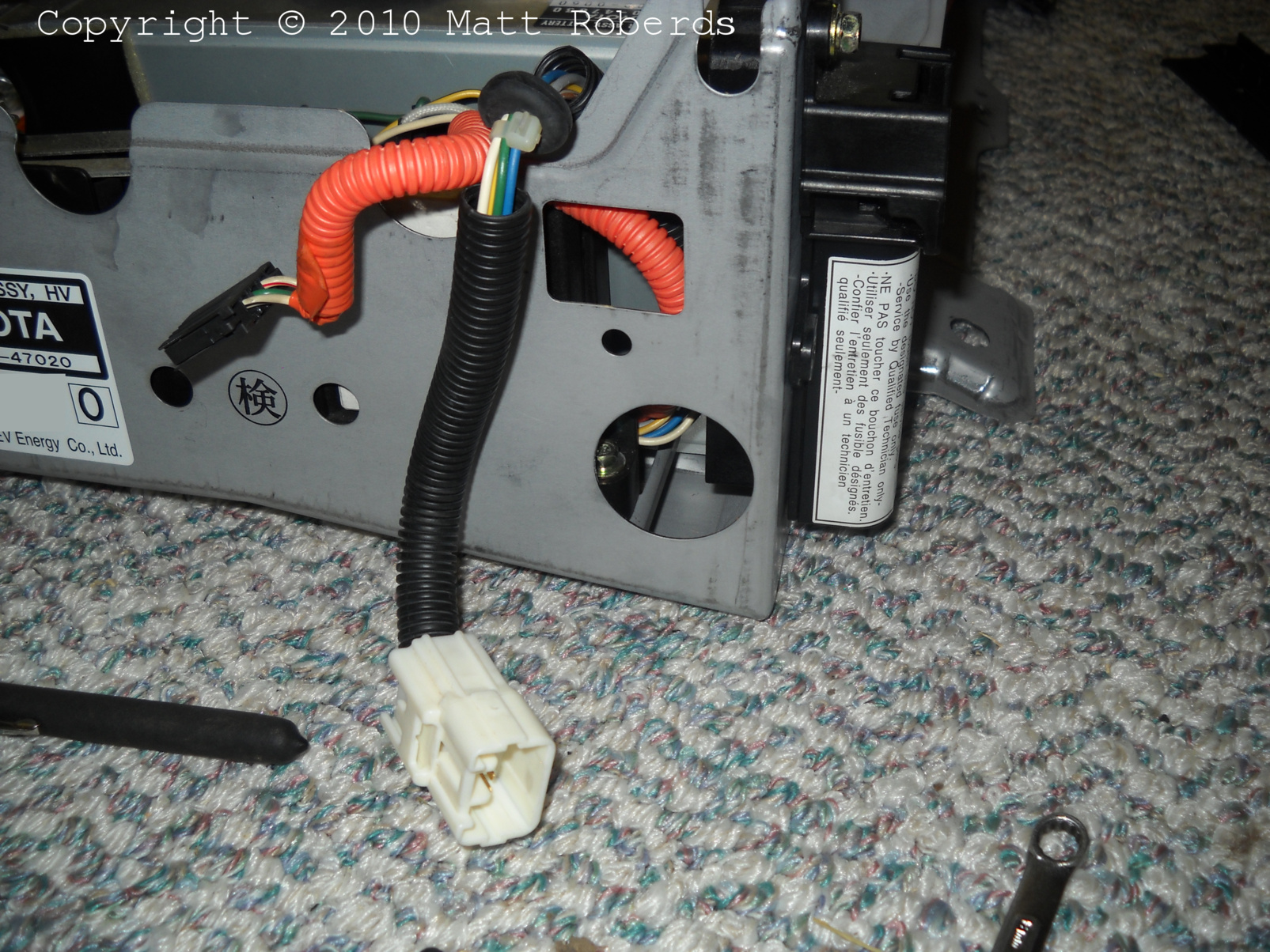
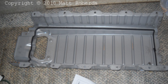
 |
This is the service plug assembly installed on the
new battery. There is no threaded hole on the center left. The bottom
right and top left holes in the case match the service plug assembly. I
used these two holes only, ending up with one extra screw. |
 |
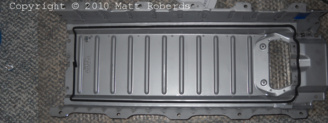
The left rear corner of the old battery. No big
hole. |
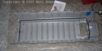
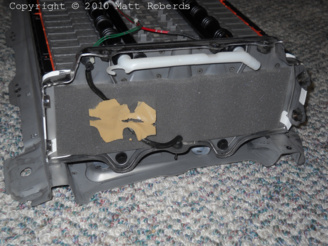
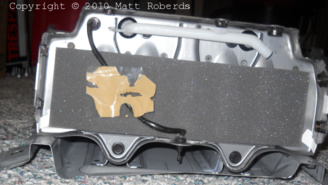
 |
The left rear corner of the new battery. Big hole,
about 1" or 2.5 cm diameter. I'm not sure what this is for. Since the
battery is air-cooled, I figured it would be good to close off this hole
before I installed the new battery in the car. I covered it with
overlapping strips of vinyl electrical tape, UL listed for 600 V and
80° C (176° F). |
Putting the new battery back in the car
 |
I put the new battery on the hand truck and took it out to the car.
This is where I put it before lifting it in to the car. The camera lens
fogged up when I took it outside...
Installation was the reverse of removal. :)
|
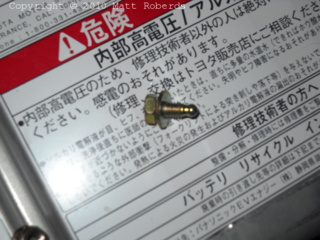 |
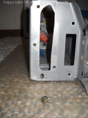
One of the two strange screws that hold the main
cables (to the inverter) on to the battery. The end is spherical; is it a
tiny corona ball? |
Epilogue
After installing the new battery, I started the car and let it idle
for several minutes, while I watched for warning lights and indications on
the multi-function display. I didn't get any. I then drove it carefully
around the block in my neighborhood, which went OK. I took a longer trip
around the neighborhood - OK. I drove to the next town, staying off the
Interstate - OK. I got on the Interstate and drove about 9 miles (14 km),
turned around, and drove about 19 miles (30 km) back home - OK. A couple of
days later, I started driving it on my regular commute to work (about 40
miles (64 km) one way) - OK.
The car now has 183,000 miles (294,000 km) on it - the new battery has
been in service for 61,000 miles (98,000 km) and about 2 years, 7 months. I
have not had any problems with the new battery so far. When I first installed
the new battery, I did not notice any mileage improvement immediately, but
after a few weeks, I thought I saw an improvement of a few miles per gallon.
(I have the raw data on this, but I have not yet studied it to see exactly
what the improvement was.)
Powered by gtkam, Gimp, ImageMagick, and, of course, vi.
Copyright © 2010-2013 Matt Roberds
Last updated Fri Feb 8 20:11:22 CST 2013